Magnetic-backed phone case that snaps to a ball-joint car mount
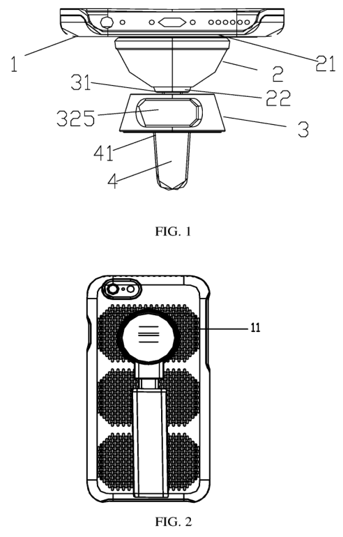
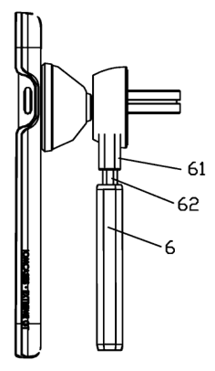
This is a phone case plus mount system: the case has a metal plate on its back, a stand/mount has a magnet that snaps to that plate, and the mount connects through a ball-and-socket rotating portion to a spring-actuated clamp that opens with a press switch. It's aimed at drivers who want an adjustable car phone mount; a selfie-stick attachment is also disclosed.
(57) What the patent covered
The main independent claim covered a four-part system: a mobile phone shell with a metal portion on its back; a securing portion with a front-mounted magnet that magnetically snaps to that metal portion and a rear end fixed to the rotating portion; a rotating portion whose rotating side is a round ball and whose securing side has a rounded groove (ball-socket) with a groove depth greater than the ball radius but less than the ball diameter; and a holding portion coupled to the rotating portion with a press switch on top of the securing side that opens and closes the holding portion.
The distinctive part: Combines magnetic snap attachment between a phone case metal plate and a magnetic securing piece with a specific shallow ball-socket geometry and a press-activated clamp.
Novelty 3/5. Magnetic phone mounts and ball‑joint swivel mounts were common when filed; the patent’s contribution is a particular ball‑groove depth and an integrated press‑switch clamp tying those together.
Making it
Injection-molded plastic bodies for the shell, rotating portion and clamp; stamped/laser-cut metal plate bonded into the case back; press-fit or glued neodymium magnet; simple assembly of ball into socket with spring and switch components.
Materials: ABS or PC injection‑molded plastic (case and mount body), steel or plated metal plate in the phone shell, rare‑earth magnet (neodymium) in the securing portion, stainless or spring steel for clamp spring components
Manufacturability 4/5. Several simple molded and stamped parts plus springs and a switch; assembly requires inserting the ball into the socket and fitting magnet/plate but no precision electronics.
Is anyone buying?
This design, or something very close to it, is on sale now. Multiple sellers offer magnetic car mounts with 360° ball joints and spring clamps; real listings show 360° rotation and clamp-based loading, with US shipping and return options.
- Magnetic Car Mount for Car AC Vent · Target (Nakedcellphone)11.95
- Universal 360° Dashboard Phone Holder with Spring Clamp · BoltHut
This demand check was run with a web search in the week of Sep 14, 2026. Listings change often, so treat it as a starting point for your own research.
Who buys it: drivers wanting an adjustable magnetic phone mount
Before you make it
We didn't find any related continuation or divisional patents still in force, although that doesn't rule out design patents, trademarks or unrelated patents covering the same product.
Practical risks include crowded market of magnetic car mounts and potential vehicle-safety regulations; the patent is specific about the ball-groove depth, so its protection was narrow.
Owners occasionally revive lapsed patents (about 1.5% are), and this page is a research lead rather than legal advice, so get a freedom-to-operate opinion before you manufacture anything.